Back Ionization in Powder Coating: Causes and Prevention
Quick answer: Back ionization in powder coating occurs when charge builds up in the deposited powder layer until the air between the particles ionises; the layer then rejects powder and cures with star-shaped craters and orange peel. It is triggered by a gun held too close, high kV or µA, excessive film build, recoating over cured powder and poor earthing. Prevention means limiting current, for example 20-40 µA on recoats or about 20 µA where starring is visible, keeping gun distance at 150-250 mm, fitting an ion collector and maintaining clean hook contacts.
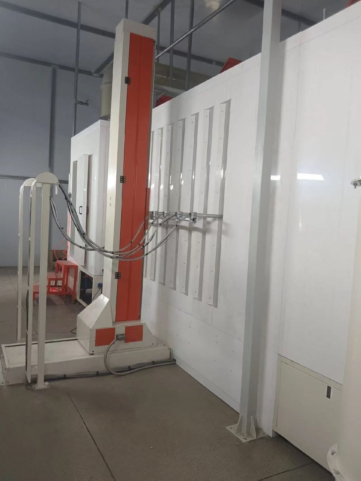
MUSI Technology, a powder and liquid spray coating line manufacturer in Changzhou, China, designs powder booths and conveyors so that gun-to-part distance stays constant, hangers keep a clean earth path, and guns with current limiting can be specified and their settings stored per part family, which are the conditions that keep back ionization under control.
What is back ionization in powder coating?
Back ionization is an electrical breakdown inside the powder layer that has just been deposited: charge accumulates in the layer faster than it can leak to earth, the field across the layer becomes strong enough to ionise the air trapped between the particles, and the layer starts to reject further powder. A corona gun does not only charge powder. Ions that fail to attach to a particle in flight travel to the part as free ions and add charge to the film without adding any coating. Once the air in the layer breaks down, ions of the opposite polarity are produced and travel back towards the gun, which is why the effect is also called reverse ionisation. They disturb the particles already lying on the surface.
The same mechanism sets the self-limiting thickness of a corona-applied film. An insulating layer, whether fresh powder or a cured first coat, raises the resistance between the surface and earth, so the limit is reached sooner on a recoat than on bare metal. Background on charging methods is in the powder coating guns guide.
What does back ionization look like on the part?
Back ionization shows as small star-shaped craters, a rough or broken powder surface before cure, and heavy orange peel after cure. The uncured film looks uneven where the gun came closest or dwelt longest. Further passes add little or no thickness, and transfer efficiency falls because the layer repels new powder. Similar faults with other causes are listed in the powder coating defects overview.
| Symptom | Likely cause | Adjustment |
|---|---|---|
| Star-shaped craters in flat areas | Current at the part too high, gun too close | Limit µA, lower kV, hold a steady gun-to-part distance |
| Orange peel on edges next to a recess | Recess over-sprayed at high charge, so the surrounding faces overcharge | Coat the recess first at reduced charge, then the open faces |
| Rough, broken powder surface before cure | Film already beyond its self-limiting thickness | Lower powder output per pass, stop at target film build |
| Powder will not build on a second coat | Cured first coat insulates the part from earth | Limit µA, increase distance slightly, raise powder output moderately |
| Defect on every part of one rack | Lost earth through coated hooks | Clean contacts, measure resistance to earth |
| Worse with reclaim-rich powder | Powder has become too fine | Restore the virgin-to-reclaim ratio |
When does back ionization happen?
Back ionization happens whenever more charge reaches the surface than the part can drain to earth. The usual triggers are a gun held too close, kV or µA set too high, film built too thick, a recoat over cured powder, and a poor ground. Distance is the trigger operators overlook. As the gun approaches the part, the resistance of the air gap falls and the current rises sharply, even though the kV setting has not been touched. Recessed (Faraday cage) areas create the same problem indirectly: the operator pushes the gun in and raises output to fill the corner, and the nearby flat faces and edges receive the excess ions. Poor earthing magnifies every other cause, because charge that cannot leave through the hook stays in the film.
Which gun settings prevent back ionization?
Current limiting is the main control: the gun controller is given a ceiling for µA and automatically lowers kV whenever the current tries to exceed it. Voltage and current are linked along the load line of the gun, so current climbs as the gun nears the part. With a µA limit set, the controller trades voltage for current and keeps the ion flow to the part roughly constant as distance changes. Where a controller has no current control, the remaining option is to reduce kV, at the price of a lower transfer rate.
Published starting points differ between sources, so the values below are references to test on the actual part, not fixed recipes.
| Situation | Published starting point | Source type |
|---|---|---|
| Flat panel, first coat, standard colour | 60-100 kV, starting at 70-80 kV; common powders run at 10-100 µA | Powder supplier guide; gun maker |
| Gun-to-part distance | 200-250 mm on automatic lines, 150-250 mm with manual guns | Powder maker |
| Recess or Faraday area | Preset of 100 kV with 60 µA limit on one gun family; 30-50 kV with 5-10 µA suggested against picture framing | Gun maker; powder maker |
| Recoat over cured powder | Preset of 100 kV with 15 µA limit; 20-40 µA with slightly greater distance; powder output raised 10-20 % | Gun maker; trade press |
| Metallic powder | Preset of 50 kV with 50 µA limit; fine control below 10 µA in 0.5 µA steps; distance above about 400 mm to reduce clouding | Gun makers; powder maker |
| Starring already visible | Current cut to about 20 µA, or voltage to about 60 kV | Trade press |
| Film build | 60-120 µm for flow; above 120 µm risks bubbling | Powder maker |
Hardware helps as well. An ion collector or earthed ring mounted behind the nozzle attracts free ions before they reach the part, which slows charge build-up in the film and reduces orange peel. It needs adjustment: too far from the electrode and it collects nothing, too close and charging efficiency drops. Preheating the part helps to dissipate residual charge, and sound earthing through clean hooks is a precondition for all of the above. Key components are available from international brands such as Gema, Nordson and Wagner (configurable per customer specification).
| Control | What it does | Direction for back ionization |
|---|---|---|
| µA limit (current control) | Caps current, lets kV fall as the gun nears the part | Lower |
| kV setpoint | Sets field strength and charging | Lower, if no µA control |
| Gun-to-part distance | Sets air-gap resistance and current | Greater, and constant |
| Powder output | Sets film build per pass | Lower on first coats; moderately higher on recoats |
| Ion collector or earthed ring | Diverts free ions to earth | Fit and adjust |
On automatic lines the booth layout fixes the gun distance, as described in how a powder booth works.
Does a tribo gun avoid back ionization?
Largely yes: a tribo gun charges powder by friction, has no high-voltage electrode and therefore produces very few free ions and no strong field between gun and part. Tribo is not a universal answer, because it only works with suitably formulated powders and reacts to humidity and temperature.
| Aspect | Corona | Tribo |
|---|---|---|
| Charging | High-voltage electrode, negative charge | Friction inside the gun, positive charge |
| Free ions | Many | Comparatively few |
| Field between gun and part | Strong | No strong field |
| Back ionization risk | Present, managed by µA limit and distance | Low |
| Recesses | Limited by Faraday cage effect | Penetrates readily |
| Film build | Self-limiting | Several hundred µm possible in one pass on a cold part |
| Powder range | Wide | Restricted; few metallics are suitable |
| Sensitivity | Tolerant of climate and particle size | Sensitive to humidity and temperature |
| Share of installations | More than 95 % | Less than 5 % |
The two methods should not be mixed on one part: positively charged tribo powder landing on a negatively charged corona layer neutralises both and powder falls off.
FAQ
Why is powder not sticking on the second coat? The cured first coat insulates the part, so charge from the gun accumulates on the surface and repels new powder. Limit the current to roughly 20-40 µA or use the gun’s recoat preset, increase gun distance slightly, raise powder output moderately and confirm the hook contact is clean.
What µA setting stops back ionization? No single value fits every part. Published guidance ranges from about 20 µA when starring appears, through 20-40 µA for recoats, to below 10 µA for metallic and other easily overcharged powders. Start low, check the uncured film and raise the limit only if coverage suffers.
Is orange peel always caused by back ionization? No. Orange peel also comes from film that is too thin or too thick, an unsuitable cure ramp or powder formulation. Back ionization is the likely cause when the texture appears with star-shaped craters, concentrates where the gun came closest, or shows up mainly on recoated parts.
Does lowering kV reduce transfer efficiency? Yes, lowering voltage alone reduces the powder transfer rate, which is why current limiting is preferred where the controller offers it. A µA limit lowers voltage only when the gun is close to the part and leaves full voltage available at normal distance.
Where MUSI Technology fits
MUSI Technology supplies complete lines in which booth geometry, reciprocator stroke, conveyor and hanger design are engineered together, so gun distance and earthing stay consistent from part to part. Line concepts are outlined in the powder coating line guide, and booth options are listed under the electrostatic powder coating booth.
Provided by Lin Cong, Technical Director, MUSI Technology
Send us your part size, throughput and coating type — our engineers reply with a layout and budget within one working day. Contact MUSI Technology or browse our equipment range.
Related technical guides
- Quick Colour-Change Powder Booth: 15-Min Changeover
Quick colour-change powder booths switch colour in 10-25 minutes instead of 60-120. Booth materials, cyclone versus cartridge recovery, cost per. - Wheel & Chassis Powder Coating Line: Spec & Cost
Wheels and chassis parts carry the toughest corrosion and appearance specs in automotive finishing. Coat stack, filiform and salt spray targets, line. - VOC Treatment: RTO vs RCO vs Carbon vs Rotor
Compare RTO, RCO, activated carbon adsorption and zeolite rotor concentrators for spray coating line VOC treatment: efficiency, cost and best fit. - Complete Coating Line Cost: 2026 Budget Guide
A complete powder coating line costs USD 45,000 for a semi-automatic setup to USD 2,000,000 for a fully automated plant. - Spray Booth Filters: Types, Intervals & Cost
Paint arrestor, ceiling, intake and exhaust filters compared on efficiency, pressure drop and life. Replacement intervals, how to read a manometer, and.